
One day Mr. Pandey, operator at a chemical plant, was overseeing the raw material unloading from the truck to the storage tank. The pump for unloading this thick raw material was a positive displacement (PD) gear pump. Suddenly, the level gauge at the tank blew overfill alarm. With great alacrity, Pandeyji closed the discharge valve on the pump, and shouted victoriously, “I saved the liquid to spill from the tank otherwise this whole place would have been a mess.”
And the coupling broke!
Thank God coupling gave way- it could have been worse. Will you help Pandeyji figure out why the coupling broke?
When Pandeyji closed the discharge valve on the pipe line, the pump was still rotating. As we discussed in our earlier post, PD pump develops constant flow with every turn of the shaft- regardless of the differential pressure on the pump. Since the liquid had no place to go and the liquid could not be compressed, the pressure on the discharge line kept increasing.
Unlike centrifugal pump, where the shut off head condition (zero flow) results in such a case, PD pump keep building pressure until something gives way- a burst pipe, a burned motor, a broken pump, and so forth- or as Pandeyji witnessed: a broken coupling. Such failures are catastrophic and dangerous.
To prevent this, having some form of overpressure protection either on the pump or in the system is important. Many manufacturers offer pump mounted relief valves (called internal relief valves), but other ways can accomplish the same purpose. System relief valves, rupture disks, torque limiting couplings and motor power load monitors can all be used to limit maximum attainable pressure in the pump or system.
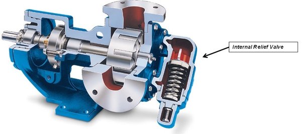
Let’s understand how the internal relief valve works. As the picture below illustrates, there is a spring pressed by a poppet. When the force on the poppet (discharge pressure multiplied by the area) is more than spring tension force, the spring will compress and the valve will begin to unseat, resulting in an open passage. The passage will allow liquid to by-pass from discharge to the suction. As the discharge pressure continues to increase, more liquid is moving back to the suction.
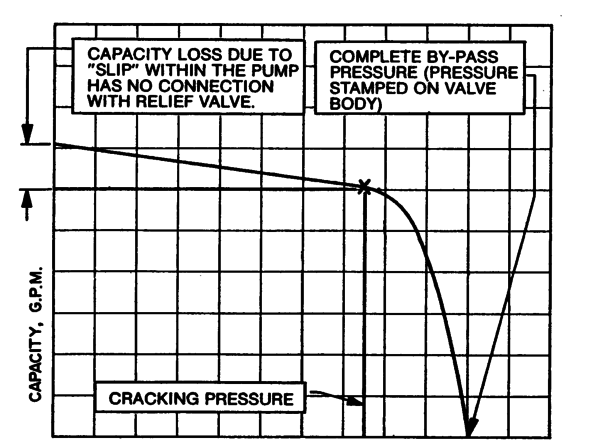
Say a gear pump is pumping against 5 bar differential pressure and its internal relief valve is spring is set to open the valve to completely by-pass at 7 bar. Actually, the relief valve starts operating at pressure less than by-pass valve setting- that is called cracking pressure. The pump will deliver full capacity at the cracking pressure. At complete by-pass pressure, the complete capacity of the pump is bypassing through the relief valve.
Though a system is designed to be continually open, inadvertent valve closing, plugged filters or other system upsets may cause enough blockages to significantly increase pressure. Overpressure protection is a must with all PD pumps - and this is often overlooked.
We will discuss in another post for certain applications whether to use an internal relief valve or an external one.
References:
1. Ten Misconceptions on Rotary PD pumps: By John Petersen, and CH Tan
Source: Pump & Systems Magazine
Link: http://www.pump-zone.com/topics/pumps/rotary-pumps/ten-misconceptions-rotary-pd-pumps
2. An Introduction to Positive Displacement Pumps
Link: http://www.engineeringtoolbox.com/positive-displacement-pumps-d_414.html
3. Relief Valve for PD Pumps- Internal or External
Link:http://www.pump-magazine.com/pump_magazine/pump_articles/article_05/article_05.htm
.